In this article
It Started as a Display Six Panels Is Not a Sphere Orientation Became the First System Boundary The Mechanical Version of the Same Problem A Spine for the System From Effects to Roles Making It Reliable Enough for the Museum Downloads and Source Files Reflections AcknowledgmentsIt Started as a Display
This project ended up teaching me the same lesson twice, once in software, and once in hardware.
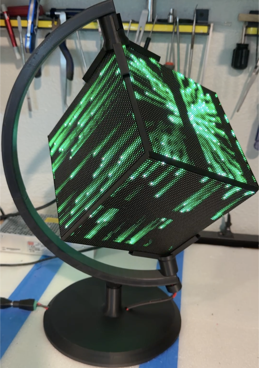
At the beginning, the idea was simple enough. Six 64 by 64 RGB LED panels, a Raspberry Pi, and something interesting to show on all six faces. A cube that lights up, spins a globe, shows some effects, and looks impressive, and commands a second look.
But that was never really the goal.
The goal was to build something I could place in my museum, turn on, and trust. Something that could run all day without needing an explanation. No loose panels. No random resets. No faces turned the wrong way. No “it worked yesterday.”
That changes the nature of the work.
Once something has to keep working, you are no longer building a project, you are building a system.
Six Panels Is Not a Sphere
The first version worked in the narrowest possible sense. Each panel displayed something. The Raspberry Pi drove the chain. The software ran. But it wasn't right.
The moment anything crossed an edge, the illusion broke.
Motion that looked right on one face did not line up on the next. Up was not always up. Left was not always left. A visual that made sense on a flat panel became confused the moment it tried to behave like a three dimensional object. Spherical projections on a flat face are just.....off.
That was the first real lesson.
Six working displays are not automatically one working cube. Face orientation is not relative to another face, it's relative to the entire collection. In other words, local correctness does not create system correctness.
Orientation Became the First System Boundary
The first software problem was orientation.
I needed a way to orient everything visually. So I built diagnostic tools that labeled each face, drew direction markers, and made the cube explain itself. The face order settled into a clear model: top, right, rear, left, front, bottom.
From there, the cube needed shared orientation logic. The software for each animation, Globe, InfoCube, MatrixCube, SolarCube, GalaxyCube, diagnostics and the all the others all had to agree about the same physical object. Otherwise every program would solve orientation its own way, and every improvement would create another exception.
Bear in mind that a Globe display could have two "North Poles". One might be at the vertex of four faces (corner "up"), another might be the center of a face (face "Up").
When changing orientations, the relative geometry of each face changes. Now create a textual display on a corner "up" or face "up" orientation and you have totally different rendering requirements.
The solution was a global coordinate system that all faces and code could share. Set the orientation of the "pole" (corner "up" or face "up") and the module renders everything correctly.
Once the software boundaries were defined, the physical boundaries became harder to ignore.
The Mechanical Version of the Same Problem
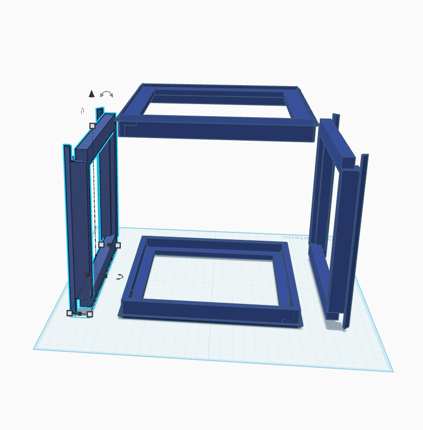
The first mechanical design was clever, and that was part of the problem.
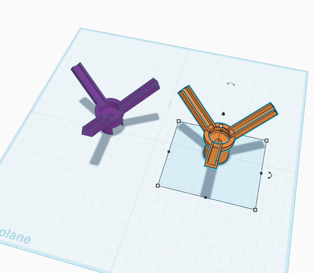
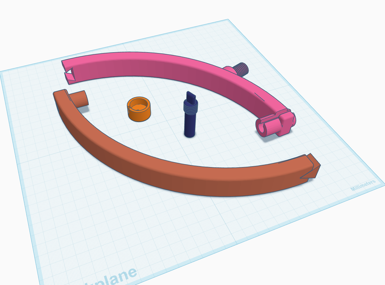
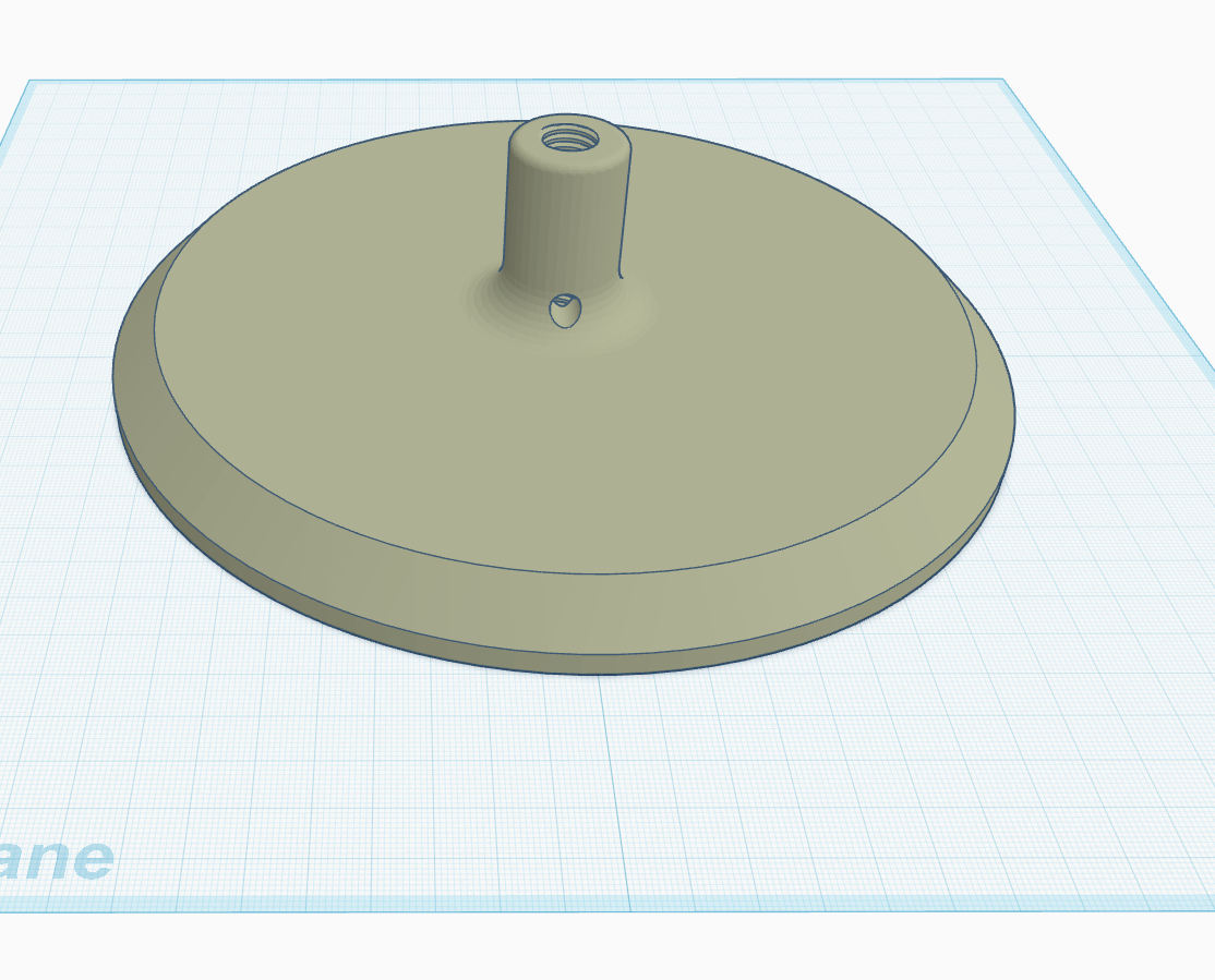
Each LED panel lived in its own printed frame. The frames came together with magnets. The whole assembly clamped into a globe style mount, tightened at the top with a thumbscrew. Three fingered jigs at the top and bottom apex helped locate the cube in the mount.
It was elegant on the screen.
In practice, it was too fragile and too dependent on everything staying perfectly aligned. Move it, and it might slip out of the jigs. Spin it and the frames wobble and became misaligned, eventually separating just enough to be noticeable. Together - it was too fragile and unstable for practical use.
The hardware was behaving exactly like the early software. Each part worked on its own, but the system did not hold together.
As is, it just wasn't ready. It needed refinement, and a different approach.
A Spine for the System
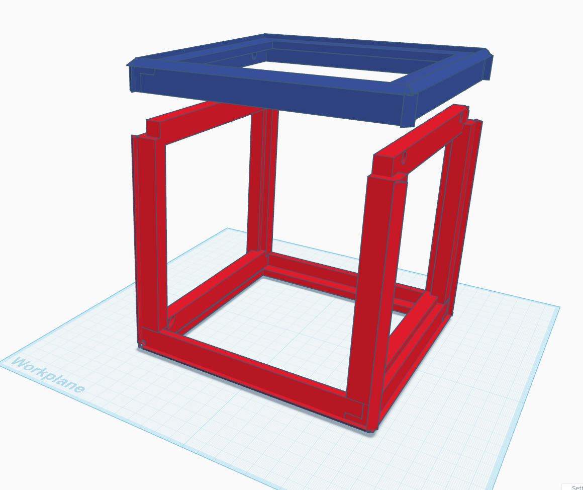
The redesign moved away from six independent frames and toward a more unified structure.
The cube became a two piece frame. Only the top is removable, and it is held in place with magnets. The rest of the structure is more rigid, more predictable, and less willing to shift around just because someone touches it.
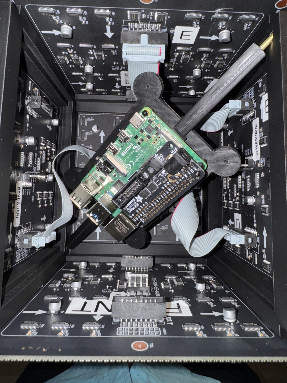
The real change was the addition of a brass rod.
A 3mm brass rod runs through the cube and into the mount, tying the structure together. It gave the cube a spine. Strength. Rigidity. Stability.
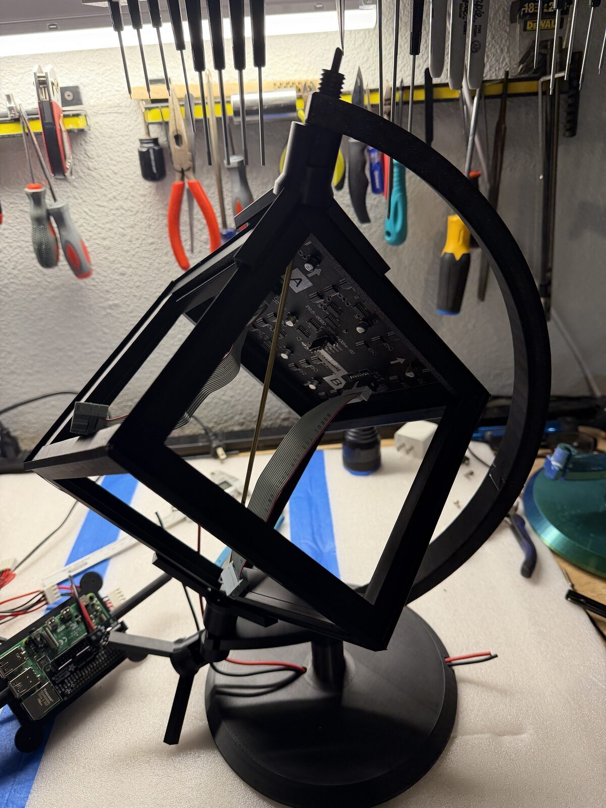
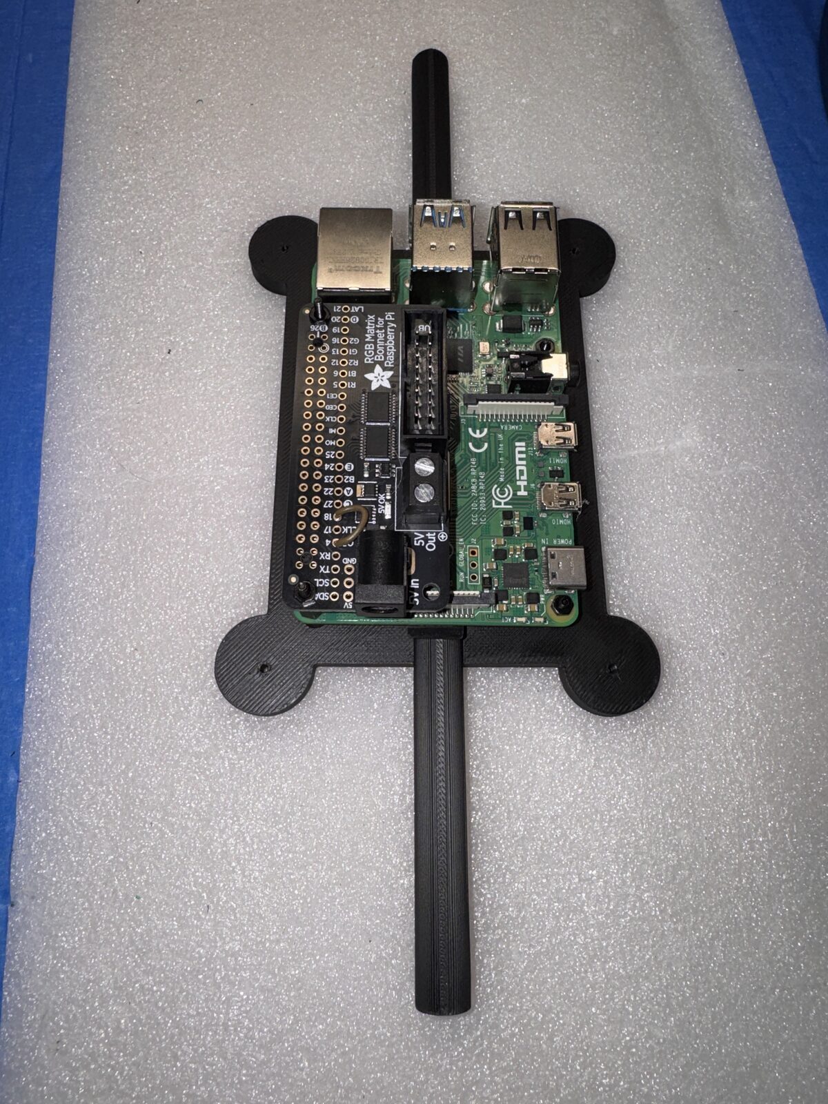
That rod also solved another problem I had been carrying around quietly. Where does the Raspberry Pi belong?
The answer was suddenly obvious. The Pi could mount to the rod, suspended in the center of the cube. Cleaner wiring. Better balance. Fewer awkward attachment points.
Physically, the rod did what the shared coordinate system did in software.
It gave everything a single reference point.
From Effects to Roles
Once the structure stabilized, the software changed too.
It stopped being a collection of effects and became a set of roles. Individual applications designed with a purpose, chained together in random sequence, designed to make an interesting, engaging display.
Globe proved the geometry. InfoCube turned the cube into a live information object, showing weather, forecast data, clock information, and system status. MatrixCube explored motion and visual continuity. SolarCube tested how orbital motion could move across faces without losing the illusion. There are others. A rotating galaxy. A calendar reminder. A series of alarms and notifications.
There is light technical detail under the surface. The cube uses the Raspberry Pi RGB LED Matrix library, chained across six panels with an Adafruit HAT mapping. Weather and calendar data are cached locally so a slow network request does not freeze the display. System stats come from the Pi itself. Shared orientation code keeps applications from reinventing the cube every time.
That was the point where the software started to match the hardware. Both were becoming less flexible in the right places, and better because of it.
Making It Reliable Enough for the Museum
Getting a project to run once is not the hard part.
Getting it to run all day is different.
That meant dealing with the boring but important parts. Local caches. Clean startup. Clean shutdown. A systemd service to cycle through modes. Command line options for rows, columns, chain length, GPIO mapping, brightness, and slowdown. Enough tuning to reduce flicker and make the display feel stable instead of nervous.
Those details do not make the cube more dramatic. They make it more trustworthy.
And for a museum display, trust matters more than novelty.
Downloads and Source Files
I am making the mechanical files and software available for anyone who wants to build on the idea.
The software is organized into modules. On the Pi, everything resides under ~/Infocube.
- Globe.cc — Renders the globes (face-up and corner-up) and defines the universal coordinate system.
- infocube.cc — Displays time, temperature, weather, and system statistics.
- solarcube.cc — Renders an animated solar system across the cube faces.
- galaxycube.cc — Simulates a rotating galaxy across all faces.
- matrixcube.cc — Generates a matrix-style animation across the cube.
- bannercube.cc — Displays a scrolling banner around the sides, with a logo or image on the top and bottom faces.
Supporting modules include:
- cube_orientation.cc — Shared orientation logic
- weather.cc — Weather data integration
- calendar.cc — Calendar data handling
- life.cc — Additional rendering logic
The package also includes a Makefile, globe image assets, and other supporting files. Extract everything into ~/Infocube and run make to compile.
A systemd service file, cube-cycle.service, is included to run the display as a service and cycle through modes automatically.
This is not packaged as a polished product. My hope is that it's something more useful than that. It is a working system, with all the thinking and iteration still visible in it.
If you want to build one, build one. If you want to change it, change it. If you find a better way to solve the mounting, orientation, rendering, or service side of the project, that is exactly the kind of thing I hope happens.
Download source code, and support files.
And here is some documentation.
Reflections
The same problems showed up in different forms.
In software, the failures happened at the seams between faces. In hardware, they happened at the seams between parts.
In both cases, the answer was not to keep adding clever fixes. The answer was to define the system more clearly.
The cube improved when the relationships became intentional. Faces knew how they connected. Parts knew how they were supported. The software knew where the data lived. The Pi knew where it belonged.
That is the part I enjoy most about projects like this.
At some point, you stop asking whether the thing works, and start asking whether it behaves.
That's when a project becomes a system.
Deeper Reflections
There’s another pattern here that shows up in almost everything I work on.
Design, at least for me, isn’t a straight path. It’s iterative. Sometimes it’s evolutionary.
I start with an idea, something that feels like it should work. Then I build it, and in the process of building it, I start to see what’s actually there. What holds up, what doesn’t, what needs to change.
I went through the same process with the Compaq and the Z-110. What started as restoration turned into improvement. Not because I set out to redesign them, but because once you understand something well enough, you start to see how it could be better.
This project followed the same path.
I needed to see the first version before I could understand what was wrong with it. And once I started improving it, those improvements didn’t just refine the original idea, they pulled it in a different direction entirely.
That’s the part that’s easy to miss.
The final design often looks intentional, like it was planned that way from the beginning. It wasn’t. It’s the result of seeing, adjusting, and sometimes letting go of the original idea altogether.
In my projects, that’s where the better design comes from.
Most designs probably evolve this way. The difference is whether you take the time to notice it.
Acknowledgments
This project would not have started without the work done by Adafruit and the broader LED matrix community. Their examples, hardware and software ecosystem, and documentation made it possible to get something working quickly enough to discover all the harder problems hiding underneath.
That is how these projects often begin. Someone else gives you the first foothold, and then the project takes you somewhere you did not expect. I hope you take this project and run with it, creating something even better. If you do, I’d be interested to see where you take it.