In this article
The PET Keyboard Problem Standing on Shared Work Parts Selection The Spacebar Problem Modern Keycaps Meet Vintage Layouts Designing the Mounting System Preserving the Original Hardware The First Power-On Phase One Complete Sharing the Files Reflections AcknowledgementsThe PET Keyboard Problem
There is something uniquely frustrating about a bad keyboard on a vintage computer.
A failed power supply can often be repaired. Bad RAM can be diagnosed. Corroded traces can be rebuilt. But keyboards are different. They are physical. Mechanical. Tactile. When they fail, the entire machine suddenly feels badly broken.
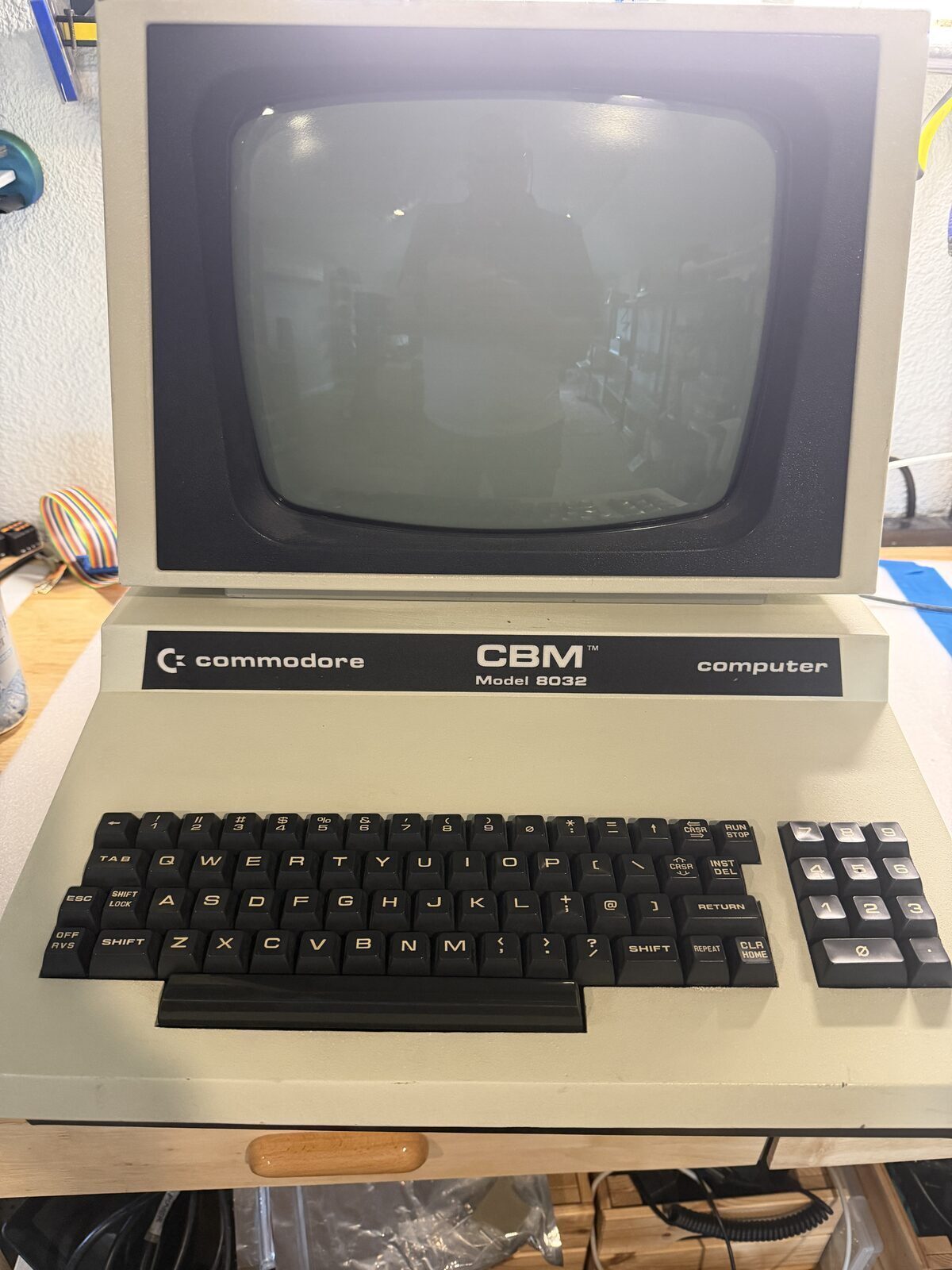
That is especially true on the Commodore PET 8032.
The PET keyboard is iconic. Heavy industrial keycaps, a distinctive layout, and a typing feel that immediately transports you back to the early days of personal computing. Unfortunately, those same keyboards are also becoming increasingly difficult to maintain. Original key switches fail. Contacts corrode. Plastic becomes brittle. The carbonized rubber membranes fail to conduct. Replacement parts are scarce, expensive, or simply unavailable.
Sure, there are repair methods. Silver conducting paint is a favorite, but then it flakes off, or wears over time, rendering the keyboard useless again. Cleaning pads is also simply a temporary fix, inevitably leading you right back to the beginning.
So this project became an exercise in balance.
How do you build a modern, reliable replacement keyboard for a PET while still preserving the originality of the machine?
For me, the answer became a phased approach.
Phase One would focus on mechanical and electrical functionality using modern components. Phase Two, later, would focus on authenticity, including custom keycaps that more closely resemble the original PET legends, height, and overall appearance.
This post documents the completion of Phase One.
Standing on Shared Work
One of the best aspects of the vintage computing community is how openly people share ideas, solutions, and technical work.
Projects like this rarely happen in complete isolation. Someone solves a difficult problem, documents the work, and others build on top of it. That collaborative spirit is a large part of why so many of these systems are still operational decades later.
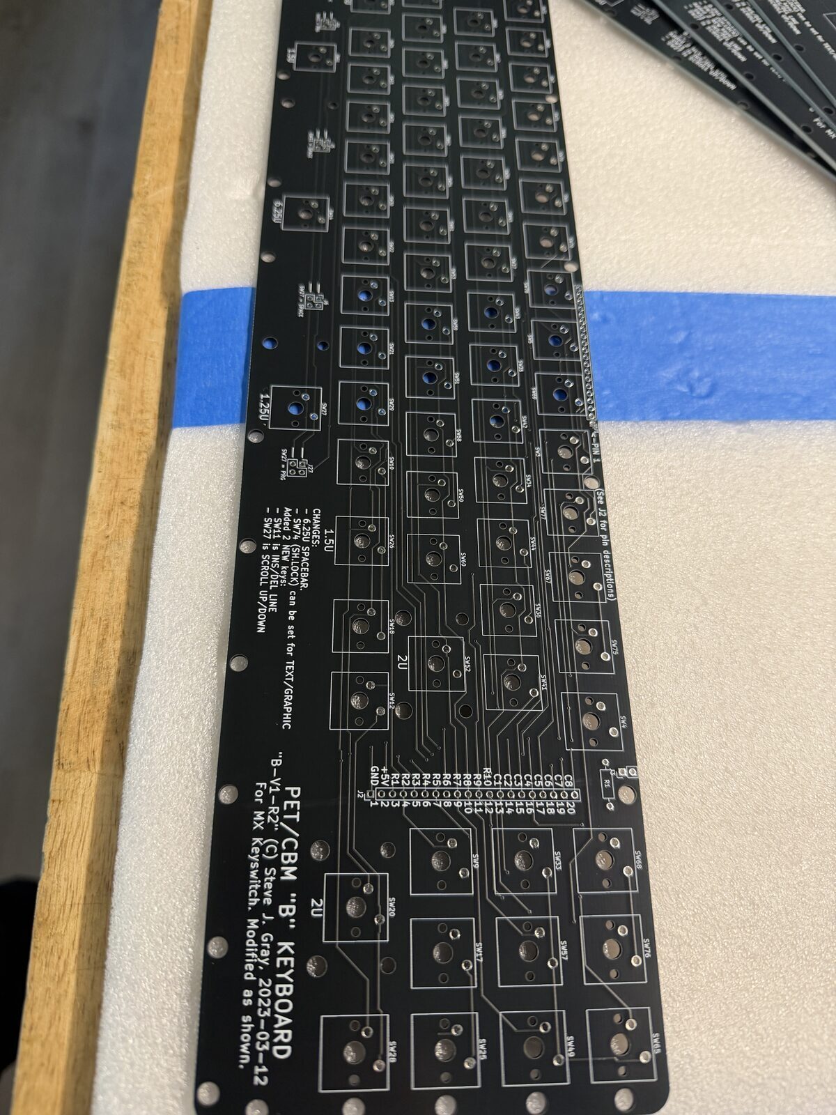
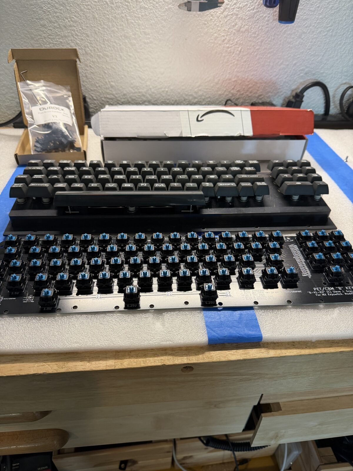
For this keyboard project, rather than designing an entirely new PCB from scratch, I started with an existing replacement PCB design and adapted the rest of the project around it.
Once I had the Gerber files, I sent them to JLCPCB for fabrication.
The turnaround was honestly impressive. Within about a week, professionally manufactured boards were sitting on my workbench.
Parts Selection
The goal for Phase One was straightforward.
I wanted to build a durable, functional keyboard using parts that are easy to source and replace.
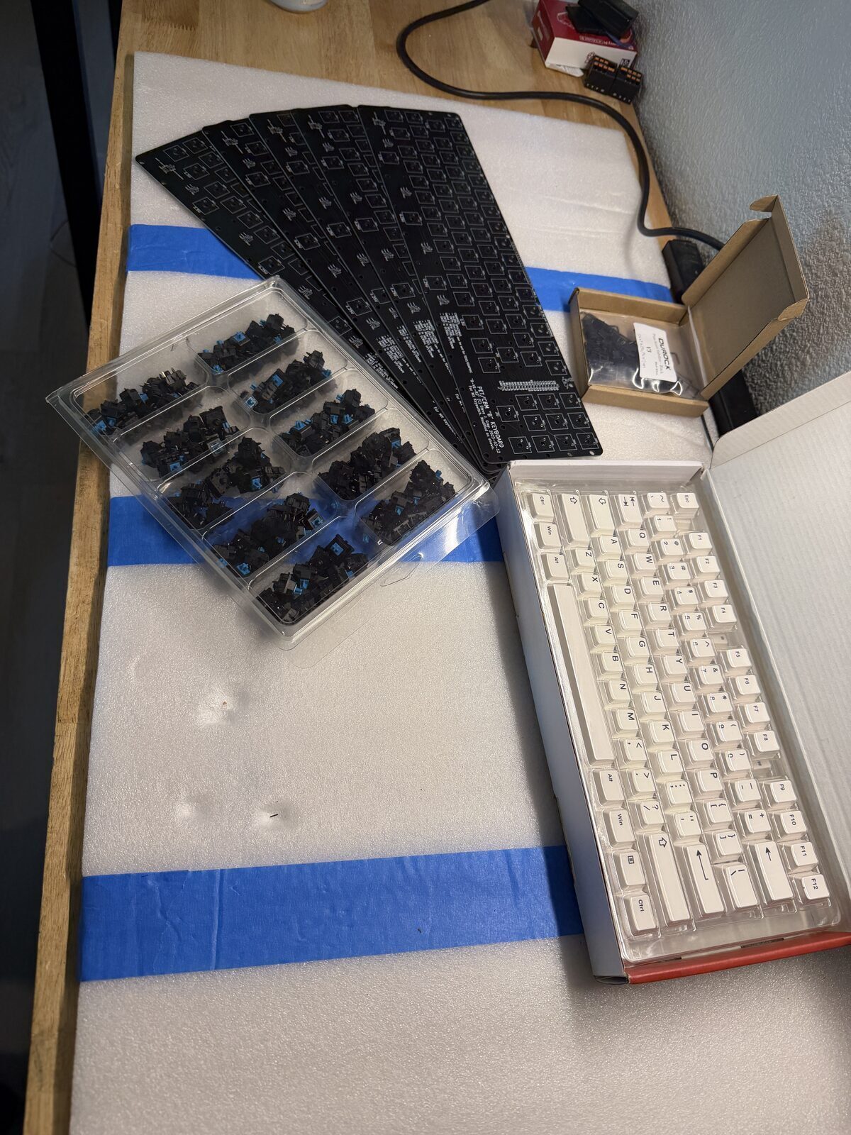
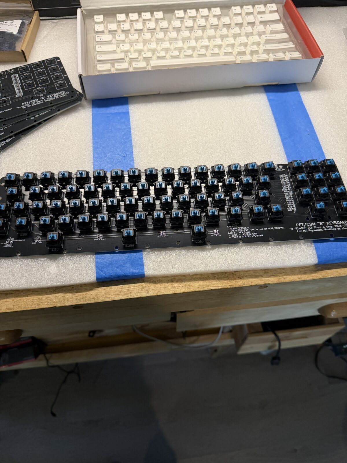
For switches, I chose MX Blue switches from Jameco, ordered in a 100-pack. Blues are loud, tactile, unapologetically clicky, and honestly feel appropriate for a machine like the PET. Quiet linear switches would have felt... wrong.
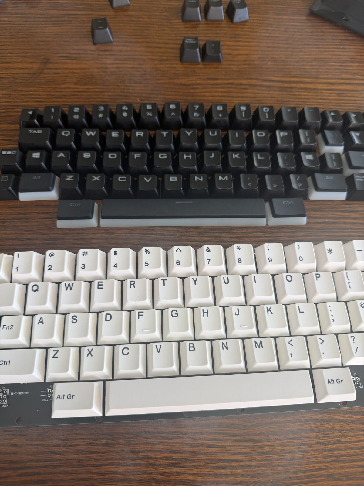
For keycaps, I intentionally went simple. I ordered a generic 107-key white keycap set from Amazon. These are obviously not authentic PET keycaps, but they let the project move forward quickly and inexpensively while keeping the door open for future customization.
I also ordered Molex single-row connectors and ribbon cable for the internal cabling.
The Spacebar Problem
One of the more interesting parts of the project involved the PET spacebar geometry.
The original PET keyboard uses unusual key sizing that does not map cleanly to modern MX layouts. This is one of the reasons replacement keyboards are not as simple as just dropping modern switches into a replica PCB.
The board design solves this with a clever compromise involving asymmetrical bottom-row spacing that accommodates a modern 6.25U spacebar while still fitting the PET layout surprisingly well.
It is one of those design decisions that reveals how much thought went into the PCB long before I ever touched the project.
Modern Keycaps Meet Vintage Layouts
One unexpected challenge involved something most people never think about until they try building a custom keyboard.
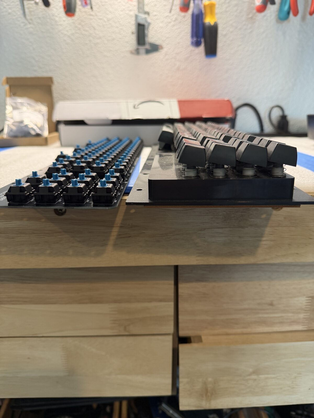
Modern keycaps are sculpted by row.
On most contemporary keyboards, each row uses a slightly different key profile and angle. The top row sits differently than the middle rows, which sit differently than the bottom row. Your fingers normally never notice because every key is already designed to live in a specific location.
But when recreating a vintage keyboard layout like the PET, things become complicated very quickly.
Sometimes the key you need simply does not exist in the profile row where you actually need to place it.
This keyboard ran directly into that issue.
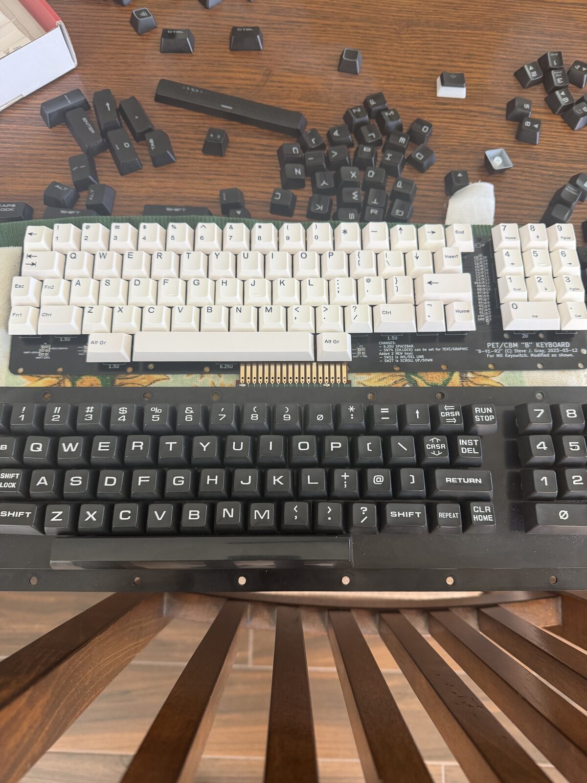
The PET places several special keys, particularly the cursor keys, in positions that do not align cleanly with modern keycap sets. Modern arrow keys are typically designed for the bottom row of a keyboard, yet on the PET layout they end up positioned much higher.
The result is functional, but visually a little odd. Certain keys sit at noticeably different heights and angles than the surrounding keys because they were never intended to occupy those positions.
It is one of those subtle details that immediately reveals the difference between adapting modern keyboard hardware and recreating a truly authentic vintage keyboard experience.
Ironically, the original PET keyboard avoided this problem entirely because Commodore used largely uniform key heights and profiles across the keyboard. The keys feel remarkably flat and consistent compared to modern sculpted layouts.
That observation heavily influenced the long-term direction for Phase Two.
The future custom keycap effort will focus not only on correct legends and appearance, but also on achieving a more uniform key profile across the entire keyboard so the finished result visually and physically resembles the original PET much more closely.
Designing the Mounting System
The PCB was only half the challenge.
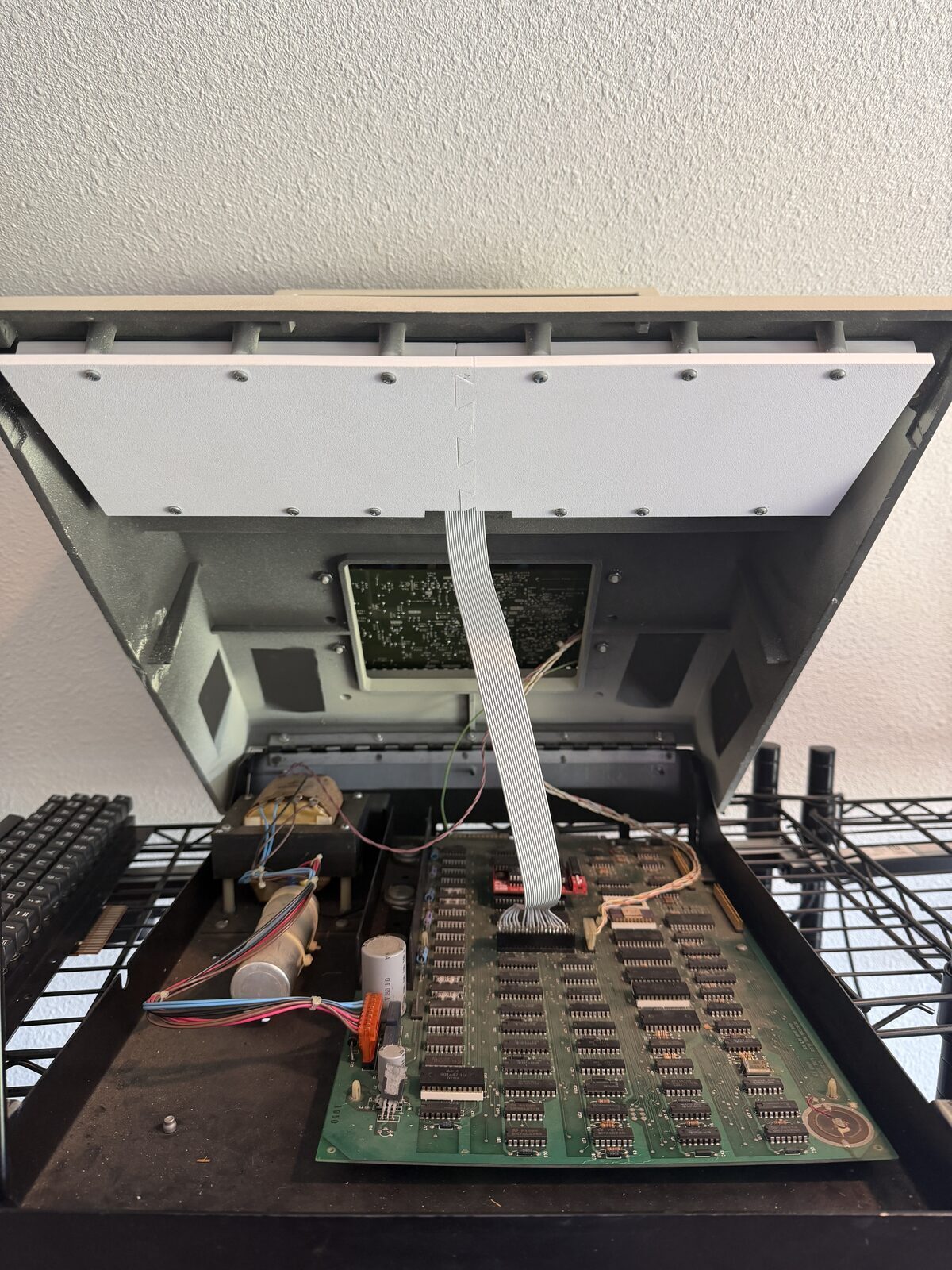
The bigger engineering problem turned out to be mounting the keyboard cleanly into the existing PET chassis while preserving alignment, fitment, and case closure tolerances.
I did not want to hack the case.
I did not want to drill new holes.
I did not want to modify the original machine in any permanent way.
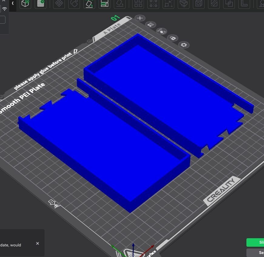
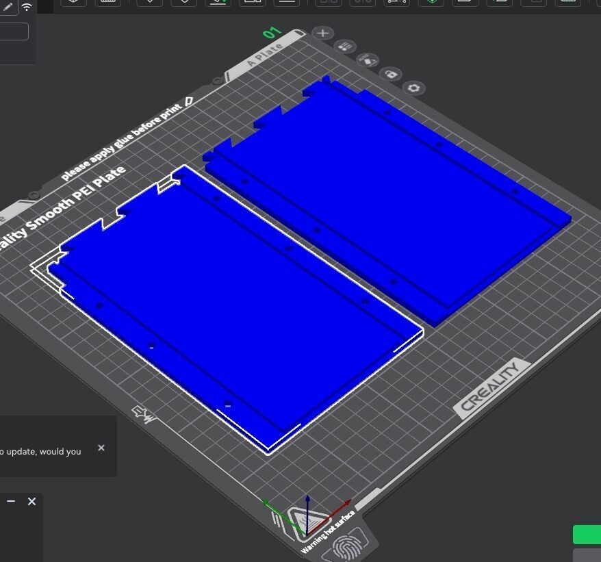
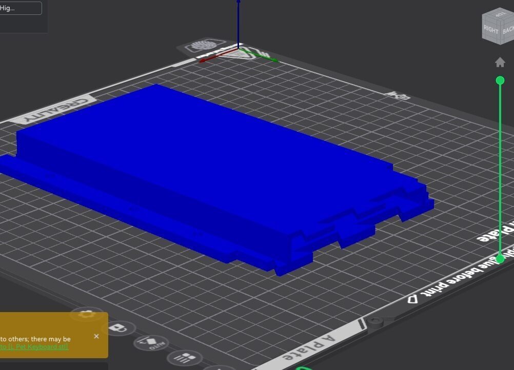
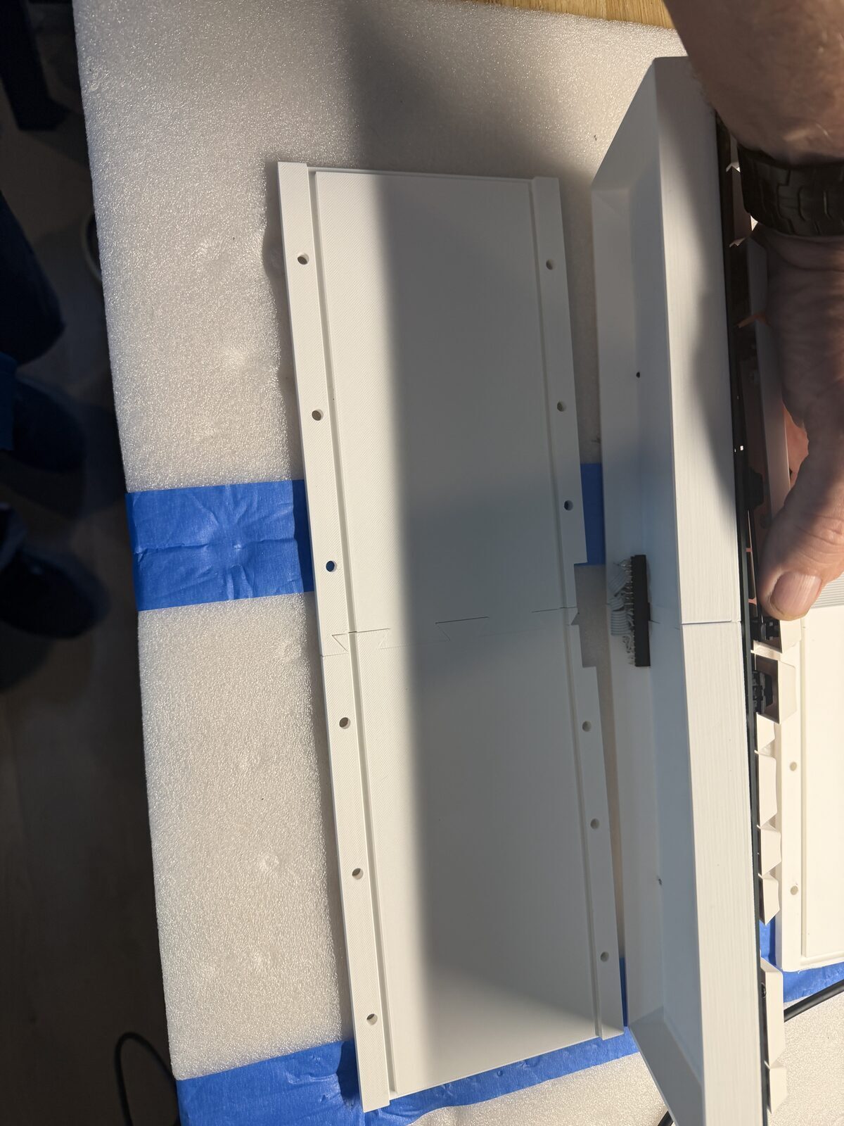
So I designed and 3D printed a custom mounting assembly that uses the original PET mounting points while positioning the replacement keyboard in the correct factory location.
That sounds simple until you actually try to do it.
There were three complete iterations of the mounting system before I finally achieved a design that aligned correctly with the original keyboard opening, used the original mounting points, maintained proper key height and spacing, and still allowed the PET case to fully close without interference.
Vintage systems rarely provide generous tolerances, and the PET certainly does not. Every millimeter mattered.
Preserving the Original Hardware
One of the goals from the beginning was preserving reversibility.
The original PET keyboard and cable remain completely untouched.
That mattered to me.
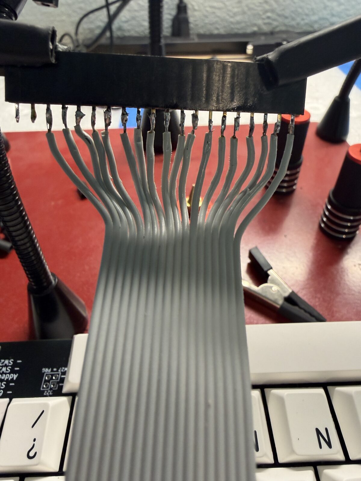
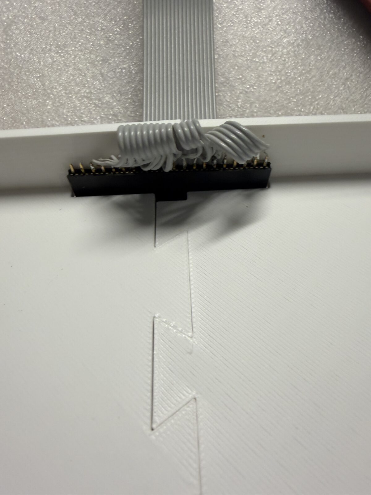
Rather than modifying the original harness, I built an adapter cable using approximately 20 inches of 18-conductor ribbon cable along with two 20-pin Molex connectors. The replacement keyboard plugs directly into the motherboard while preserving the original cable assembly intact.
At any point, the original keyboard can be reinstalled and the system returned to factory configuration.
That preservation mindset is a recurring theme throughout many of my restoration projects.
When I do replace original hardware with modern equivalents, I try very hard to ensure the replacement still follows the spirit of the original system, both mechanically and aesthetically. The goal is not to modernize these machines into something unrecognizable. The goal is to preserve the experience of using them while improving reliability and maintainability where practical.
That philosophy influenced nearly every decision in this project.
The keyboard mounting system uses the original attachment points. The replacement keyboard sits in the original location and maintains the original geometry as closely as possible. Even the future Phase Two plans are driven largely by the desire to visually recreate the appearance and feel of the original PET keyboard rather than simply accepting modern keyboard conventions.
To me, preservation is not always about keeping every electronic component original forever.
Sometimes preservation means ensuring the machine can still be powered on, typed on, demonstrated, and experienced decades later without destroying or discarding the original hardware that gave it historical value in the first place.
The First Power-On
There is always a moment where theory becomes reality.
You connect power.
You press a key.
And you wait to see whether the machine responds or releases the magic smoke.
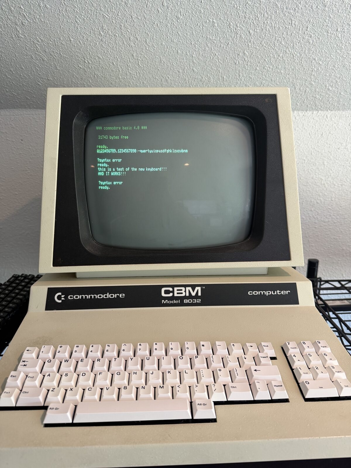
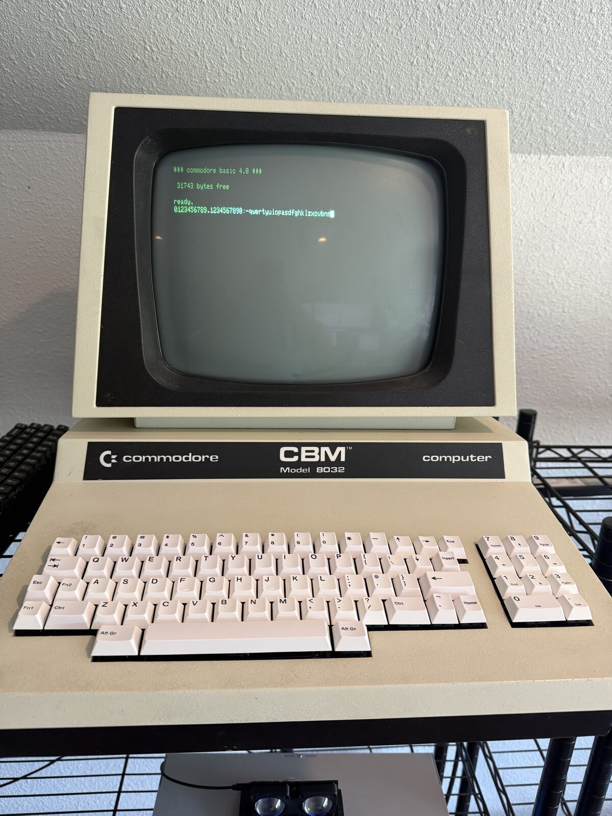
Fortunately, this time the result was exactly what I hoped for.
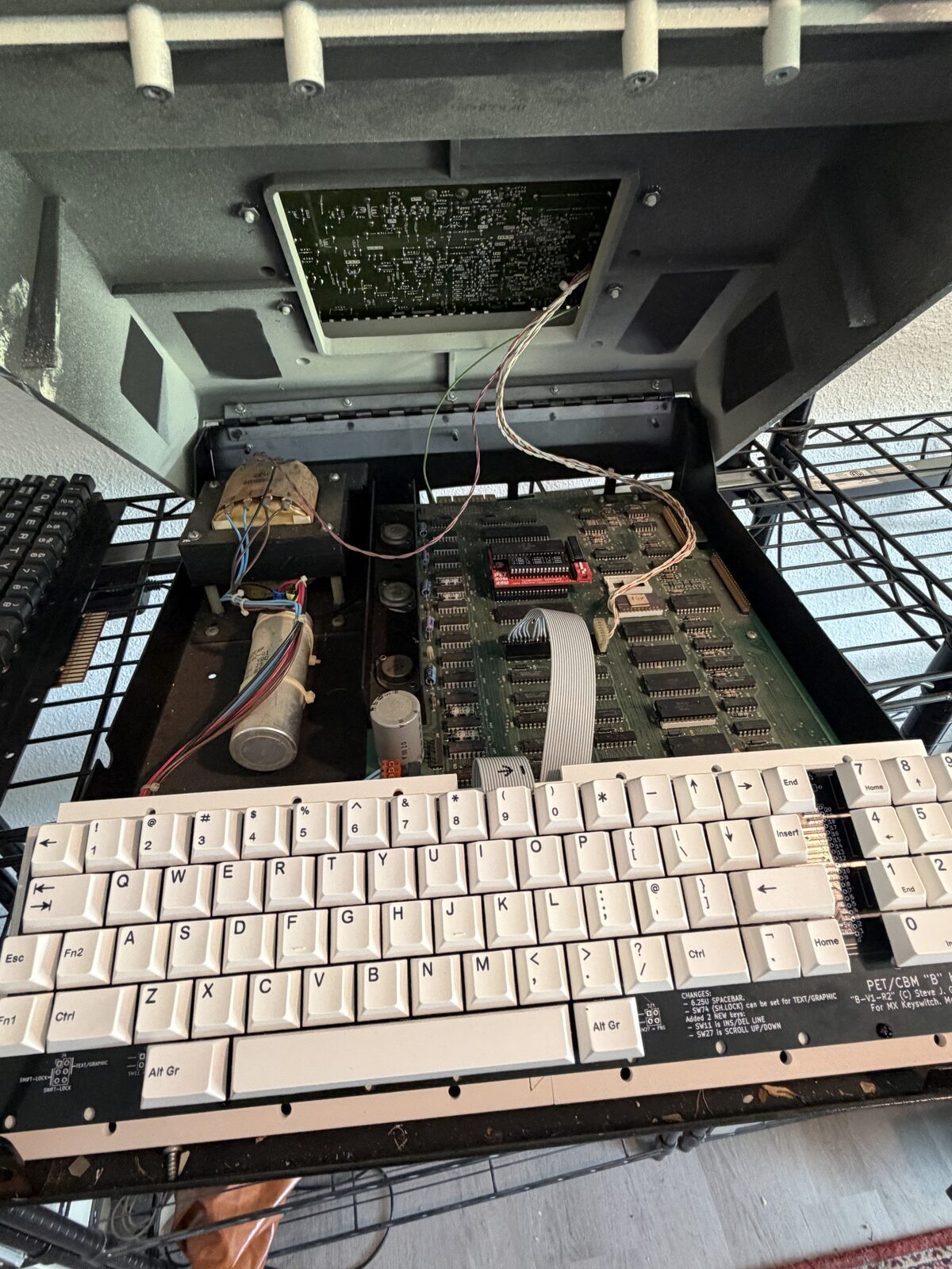
The keyboard worked.
Not partially. Not mostly.
Fully.
Every key registered correctly, the typing feel was excellent, and the PET suddenly became dramatically more usable again.
It's odd, as the keycaps can be a little misleading, but the overall vibe is exactly what I was hoping for.
Phase One Complete
At this point, the keyboard is mechanically complete and electrically complete.
The PET now has a reliable, serviceable, modern replacement keyboard while fully preserving the original hardware for the future.
That alone makes the project worthwhile.
But this is not the end of the project.
Phase Two will focus on authenticity.
The current white generic keycaps work well, but they obviously do not capture the visual character of the original PET keyboard. The long-term goal is to create custom keycaps with proper legends and a more period-correct appearance while retaining the modern MX switch foundation underneath.
That effort will also address the sculpted key profile issue by ensuring all keys share a more uniform height and appearance, much closer to the original PET keyboard design.
Sharing the Files
One of the best aspects of the vintage computing community is how openly people share solutions.
I will add links to the STL files for the mounting assembly so others can build on this work as well.
Hopefully this helps keep more PET systems operational for years to come.
Reflections
What I appreciate most about this project is that it represents a practical middle ground between preservation and usability.
Purists sometimes argue that everything should remain completely original.
Others are comfortable replacing nearly everything with modern equivalents.
I tend to land somewhere in the middle.
The original keyboard, cable, and mounting hardware remain preserved and untouched. Nothing irreversible was done to the machine. Yet the PET is now dramatically more reliable and enjoyable to use.
To me, that feels like the right balance.
Because ultimately, these machines were meant to be used.
This one is certainly useful.
Acknowledgements
Special thanks to Steve Gray for designing and sharing the PET replacement keyboard PCB that made this project possible.
The vintage computing community continues to thrive largely because people like Steve openly share engineering work, technical documentation, discoveries, and solutions that help preserve these systems for future generations.
I try to carry that same philosophy forward in my own projects as well. Just as others shared the information that made this keyboard possible, I plan to share my mounting designs, STL files, lessons learned, and related project details with the community so others can build on this work in the future.
Additional thanks to the broader restoration and maker communities whose collective knowledge continues to make projects like this achievable.